**Simulating a plane mirror using 2D images for the TWM**
Nkiruka Uzuegbunam
Virtual Plane Mirror simulation using 2D color images
===============================================================================
This post describes a method for simulating a plane mirror using 2D images of the background in the robotic mirror setup described in earlier posts. I detail the mathematics,
show some simulation results, and discuss methods of improvement in various aspects of the system. In the end, the work boils down to appropriately scaling the background according
to the user's distance from the mirror.
[Click here](../index.html) to navigate back to home page.
Previous Work in virtual mirror simulation
-------------------------------------------------------------------------------
Mirrors are used in many different applications, ranging from everyday personal care to medical use. However, they are not interactive. Virtual mirrors are interactive mirrors. Typically, they consist of a display with static depth or rgb cameras. The cameras track the user and/or the environment, creating a reflection based interaction. Often, the user views their reflections augmented with virtual objects. For instance, in virtual mirrors for fashion, the virtual objects are sunglasses, clothes, shoes, etc. In medicine, the virtual objects could be health indicators of some sort.
However, many virtual mirror display systems do not strive to be true mirrors, depicting a correct reflection based on the user's perspective. This can reduce the realism in the display. Several previous works have tackled creating proper reflection in various virtual mirror systems. [#Francois13] created a handheld virtual mirror as a prototype for geometrically correct reflections in virtual mirrors. Ignoring the user's background, they used a single static rgb camera, and magnetic sensors tracking the user's location to create their mirror reflections. With the advent of depth cameras, [#Shen13], [#Shen12], [#Straka11], and [#Su17] create virtual mirror reflections with a network of one or more depth and rgb cameras, with [#Su17] creating mirror reflections in non-planar mirror settings. [#Lee17] is a direct extension of the work of [#Francois13] in onscreen reflections as a navigation tool in camera-based systems.
In this work, we extend the work of [#Francois13] in two important ways. First, we take the user's interaction with the background as an important component of interacting with a mirror device. Second, we introduce a novel robotic system that tracks the user's location.
Estimating the Mirror Reflection
-------------------------------------------------------------------------------
The system of Francois and Kang [#Francois13] proposed a camera and screen (with magnetic sensors for user position tracking) for simulating a virtual mirror with geometrically correct reflections. In particular, their model is derived in four phases based on three key assumptions. In the first phase, objects are mapped from the 3D world to the mirror plane. Let an object be located at point P in the virtual viewer's coordinate system, Figure [virtualViewpt]. P is the point $[ X, Y, Z ]^\T$. It is mapped to a point, p, on the mirror surface $[xp, yp, d]^\T$ where d is the orthogonal distance from the virtual viewer to the mirror
plane:
![Figure [virtualViewpt]: The virtual user's viewpoint from [#Francois13]](../assets/figure2_KangFrancois.png)
\begin{equation}
\begin{bmatrix}
X_p \\
Y_p \\
Z_p
\end{bmatrix}
=
\begin{bmatrix}
d & 0 & 0 & 0\\
0 & d & 0 & 0 \\
0 & 0 & 1 & 0
\end{bmatrix}
*
\begin{bmatrix}
X \\
Y \\
Z \\
1
\end{bmatrix}
\end{equation}
Then $x_p = \frac{X_p}{Z_p} = \frac{d*X}{Z}$, and $y_p = \frac{Y_p}{Z_p} = \frac{d*Y}{Z}$
In the second phase, objects are mapped from the camera's world view into the camera's imaging plane as shown in Figure [cameraViewpt]. Two key assumptions are made here: 1) the camera is assumed to be a pinhole camera and 2) the imaging plane of the camera is assumed to coincide with that of the mirror plane. As such, we have that a point $P_c = [ X_c, Y_c, Z_c ]^\T$ in the camera coordinate system, with origin at camera center, maps to the point $p_c = [x_{pc}, y_{pc}, f]^\T$. f is the focal length of the camera.
![Figure [cameraViewpt]: The camera's viewpoint from [#Francois13]](../assets/figure3_KangFrancois_a.png)
\begin{equation}
\begin{bmatrix}
X_{pc} \\
Y_{pc} \\
Z_{pc}
\end{bmatrix}
=
\begin{bmatrix}
f & 0 & 0 & 0\\
0 & f & 0 & 0 \\
0 & 0 & 1 & 0
\end{bmatrix}
*
\begin{bmatrix}
X_c \\
Y_c \\
Z_c \\
1
\end{bmatrix}
\end{equation}
Then $x_{pc} = \frac{X_{pc}}{Z_{pc}} = \frac{f*X_c}{Z_c}$, and $y_{pc} = \frac{Y_{pc}}{Z_{pc}} = \frac{f*Y_c}{Z_c}$
The third phase consists of mapping the camera viewpoint to the virtual user's viewpoint. The key assumption here is that the image and virtual mirror planes coincide. Hence, the camera's origin is mapped to the virtual user's viewpoint via a simple translation $[t_x, t_y, t_z]^\T$ as seen in Figure [viewpt]. Then the point p in the virtual user viewpoint is related to the a point $P_c$ in the camera coordinate system as:
![Figure [viewpt]: The camera and virtual user's viewpoints from [#Francois13]](../assets/figure3_KangFrancois_b.png)
\begin{equation}
\begin{bmatrix}
X_p \\
Y_p \\
Z_p
\end{bmatrix}
=
\begin{bmatrix}
d & 0 & 0 & 0\\
0 & d & 0 & 0 \\
0 & 0 & 1 & 0
\end{bmatrix}
*
\begin{bmatrix}
X \\
Y \\
Z \\
1
\end{bmatrix}
=
\begin{bmatrix}
d & 0 & 0 & 0\\
0 & d & 0 & 0 \\
0 & 0 & 1 & 0
\end{bmatrix}
*
\begin{bmatrix}
1 & 0 & 0 & t_x\\
0 & 1 & 0 & t_y \\
0 & 0 & 1 & t_z \\
0 & 0 & 0 & 1
\end{bmatrix}
*
\begin{bmatrix}
X_c \\
Y_c \\
Z_c \\
1
\end{bmatrix}
\end{equation}
Then a point in the virtual user's mirror plane, $p = [x_p, y_p]^\T$, is defined as:
\begin{equation}
x_p = \frac{X_p}{Z_p} = \frac{d*X}{Z} = \frac{d * (X_c + t_x)}{Z_c + t_z}, \\
y_p = \frac{Y_p}{Z_p} = \frac{d*Y}{Z} = \frac{d * (Y_c + t_y)}{Z_c + t_z}
\end{equation}
In order to relate the point p in the virtual user's mirror plane to the point $p_c$ in the camera's image plane, it would be necessary to obtain 3D positions of each point in the environment. However, Francois and Kang [#Francois13] assume that as the user is the center of interest, and **not the background**, the world may be modeled as a plane parallel to the mirror plane, at the same distance as the user's viewpoint. This is termed Flat world assumption, and is shown in Figure [worldAsPlane]. Hence, the z-component of the camera coordinate system is fixed as $Z_c = f + d$. Thus, we relate p, to $p_c$ as:
![Figure [worldAsPlane]: Flat world assumption from [#Francois13]](../assets/figure5_KangFrancois.png)
\begin{equation}
x_p = \frac{X_p}{Z_p} = \frac{d*X}{Z} = \frac{d * (X_c + t_x)}{Z_c + t_z} = \frac{d * ( \frac{Z_c * x_{pc}}{f} + t_x)}{Z_c + t_z} = \frac{d * ( \frac{ (f+d) * x_{pc}}{f} + t_x)}{ (f+d) + t_z}\\
y_p = \frac{Y_p}{Z_p} = \frac{d*Y}{Z} = \frac{d * (Y_c + t_y)}{Z_c + t_z} = \frac{d * ( \frac{Z_c * y_{pc}}{f} + t_y)}{Z_c + t_z} = \frac{d * ( \frac{ (f+d) * x_{pc}}{f} + t_x)}{ (f+d) + t_z}
\end{equation}
TestBed
-------------------------------------------------------------------------------
Before continuing, I describe my testbed for the robomirror system. Built in Unity3D, it allows me to collect data as I would in the actual robomirror system. It consists of a mirror reflecting the user as they move in the environment, as well as a camera showing the user as they move in the environment.
[TO DO]: get image from unity3d
Advantages of the RoboMirror system
-------------------------------------------------------------------------------
The novelty in the robomirror system is that it provides some simplifications to the equation above that make it possible to use a 2D image for simulating a mirror.
The robomirror system consists of a camera attached to a robotic arm, capable of left-right, top-bottom (x-y) motion. The camera and arm are placed behind a one-way mirror. The user sits in front of the one-way mirror. As the user moves, the camera tracks the user's face location. The robotic arm moves in such a manner that the user's face is always in the center of the image. Hence, the **first** advantage of the robomirror system is the robomirror system tracks the x-y movements of the user. This simplifies the equation above by setting $t_x = t_y = 0$. The final translation parameter, $t_z$, that relates the camera's z-location to that of the virtual user's must still be found. Thus, our reflection equation is now:
\begin{equation}
x_p = \frac{X_p}{Z_p} = \frac{d*X}{Z} = \frac{d * (X_c + t_x)}{Z_c + t_z} = \frac{d * ( \frac{Z_c * x_{pc}}{f})}{Z_c + t_z} \\
y_p = \frac{Y_p}{Z_p} = \frac{d*Y}{Z} = \frac{d * (Y_c + t_y)}{Z_c + t_z} = \frac{d * ( \frac{Z_c * y_{pc}}{f})}{Z_c + t_z}
\label{eqn:Reflection}
\end{equation}
**[TO DO: Change this paragraph. We want to eliminate estimating t_z. Why? This reduces the warping we would need to do, and hence chance of an error. Run simulations with and without t_z as a check. In addition, eliminating t_z will allow us to calibrate the robomirror to work in a certain interaction zone. This is good because we want the user to be close to the two-way mirror for interaction, rather than farther away from it.]** The second advantage of the robomirror system is that it is designed to work when the user is in an **interaction zone**. This means that 1) the user's face is directly in front of the one-way mirror, and 2) the user's face is within a set distance from the camera for optimal interaction. This is an advantage as this narrows the conditions under which we provide a true reflection, rather than forcing us to completely recreate a true plane mirror as in computer graphics simulations. As such, we can calibrate the robomirror to ensure it works for conditions 1) and 2) as stated.
Recall, the three key assumptions of the Francois and Kang [#Francois13] system are 1) camera is a pinhole model, 2) camera's imaging plane coincides with the mirror plane and 3) the world is on a flat plane parallel to the mirror plane, at a fixed distance z = f + d. In order to create an accurate reflection, the third assumption must be violated. This creates a unique problem as it would require a 3D model of the environment, as in computer graphics simulations.
One possible alternative to the 3D model of the environment is a soft violation of the Flatworld assumption. Instead of a single flatworld, use multiple flatworlds. In this case, the user is still located at d, while the background and foreground are divided into depth layers $d_i$.
Another possible alternative to the 3D model comes from [#Francois13]. As stated in [#Francois13], the mirror image the user sees depends on the user's perpendicular distance to the mirror, d. In fact, we observe that the image also appears to be a scaled version of a larger 2D background image. If we can model the relationship between scaling and distance to the mirror, we should be able to create the appropriate 2D background image for a good reflection. This is standard computer vision, which I need to check up again.
Alternative One: Multiple Flatworlds
-------------------------------------------------------------------------------
Our present reflection equation is given in equation \ref{eqn:Reflection}. Modifying the equation for multiple flatworlds $d_i$ involves estimating the pixels for various values of $d_i$. For instance, assume $d_i = \{ d_1, d_2, d_3, ..., d, d_4, d_5, ..., d_N \}$. where d is user's distance, and $d_i$ are depth distances from camera (to get distance to imaging plane, subtract f). Then, we replace Zc with $ Zc = f + d_i $. Hence, the equation for reflection becomes:
\begin{equation}
x_{pi} = \frac{d * ( \frac{ (f + d_i) * x_{pci} }{f})}{ f + d_i + t_z} \\
y_{pi} = \frac{d * ( \frac{ (f + d_i) * y_{pci} }{f})}{ f + d_i + t_z}
\label{eqn:mult_Reflection}
\end{equation}
where $y_pi, x_{pi}$ are the set of pixels at depth $d_i$.
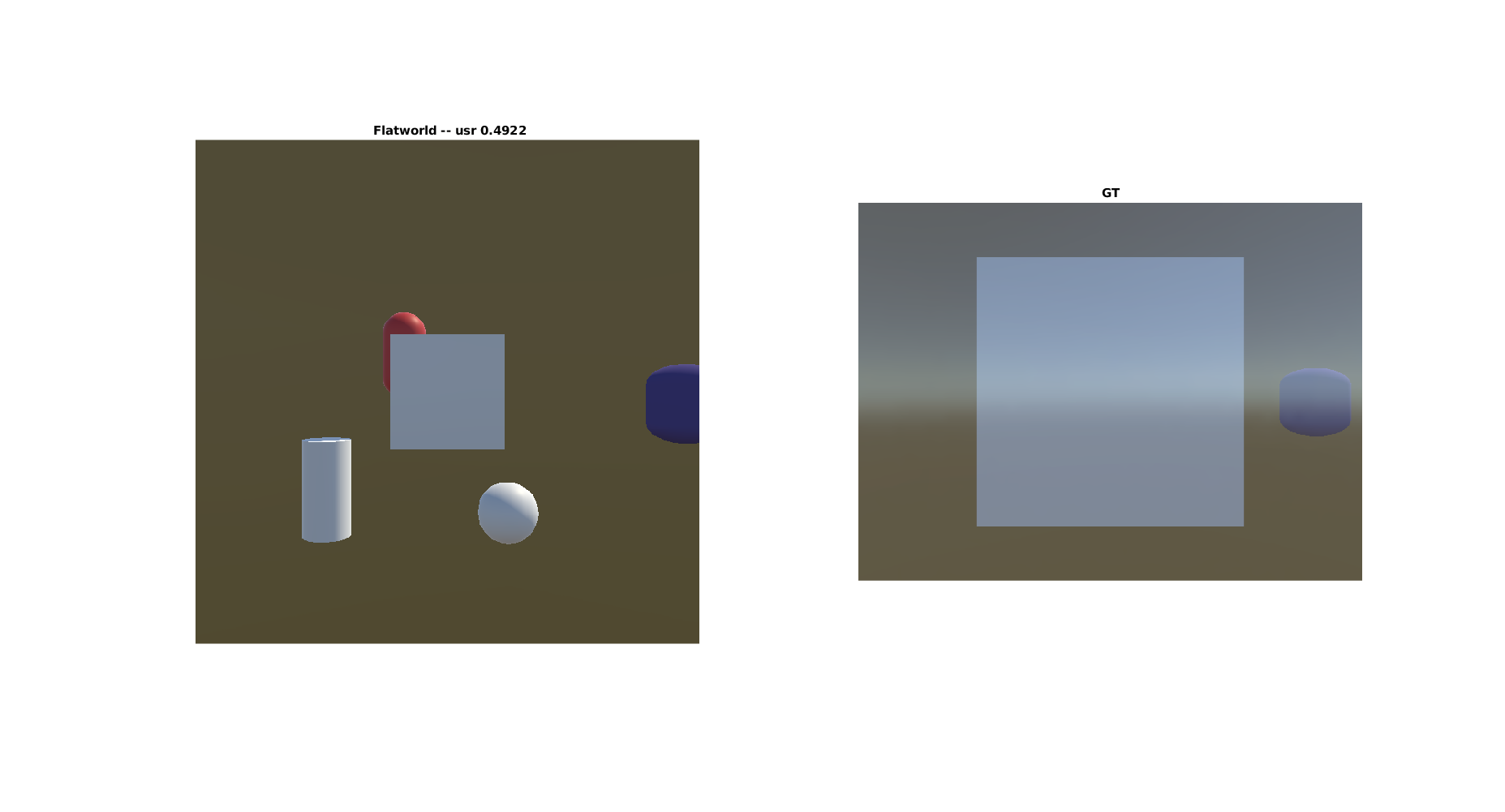
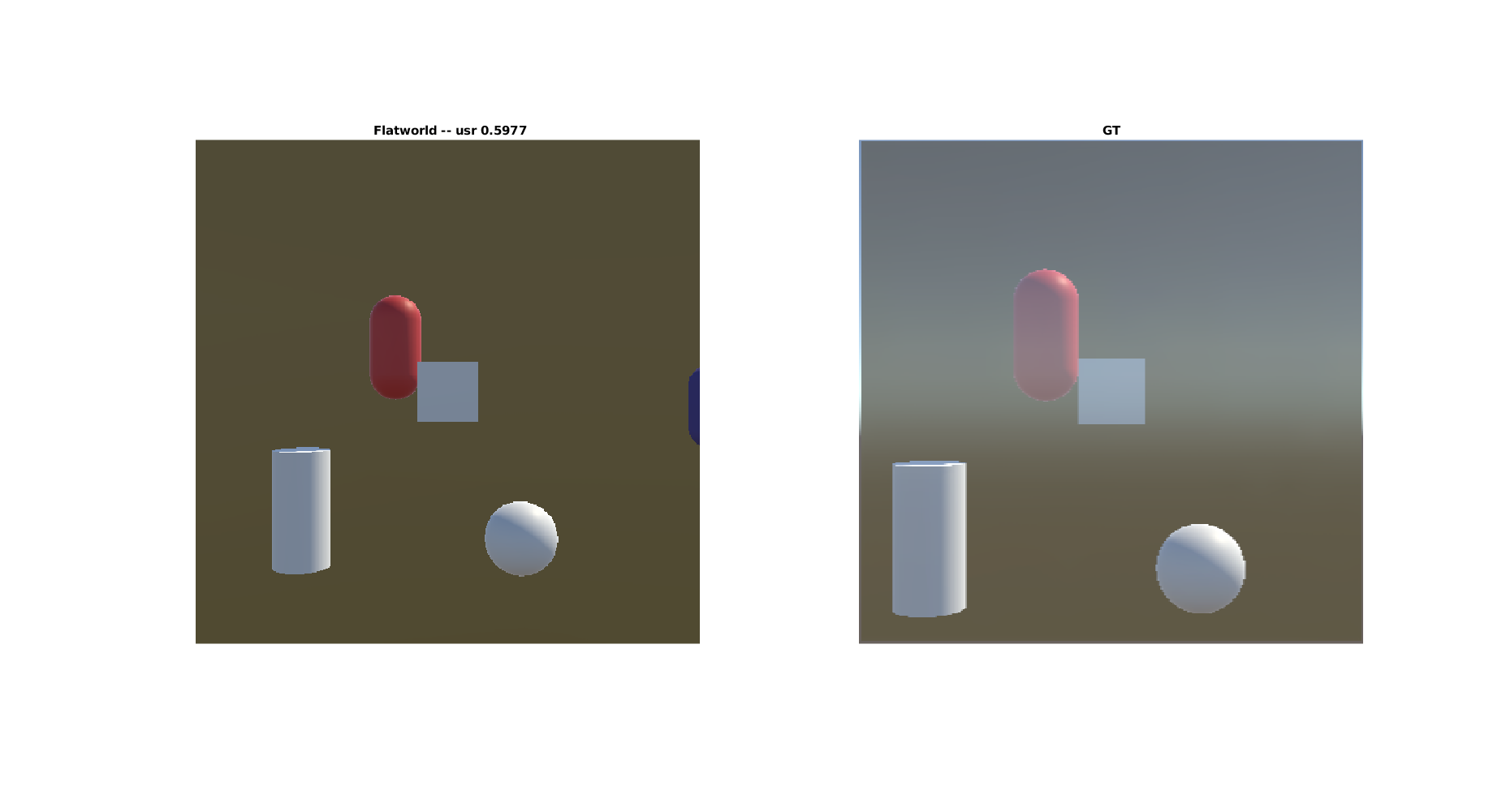
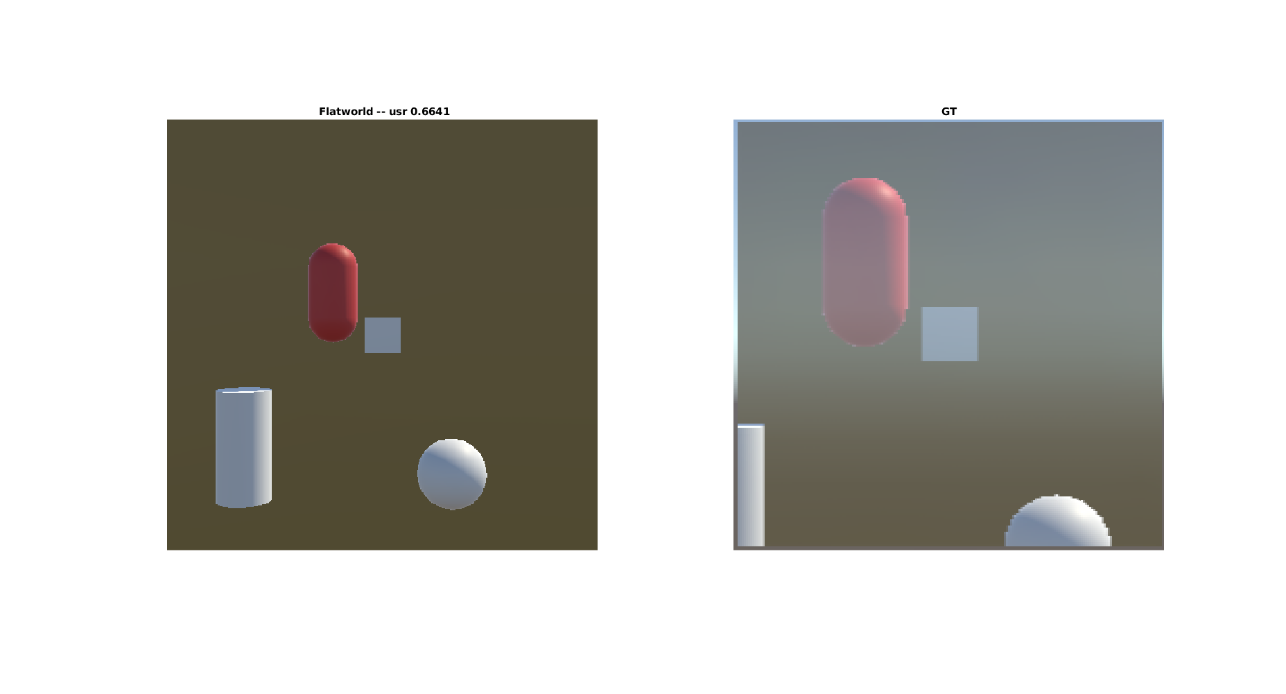
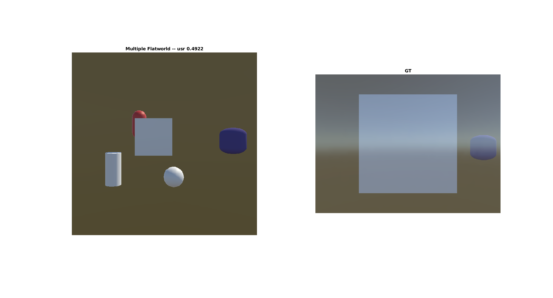
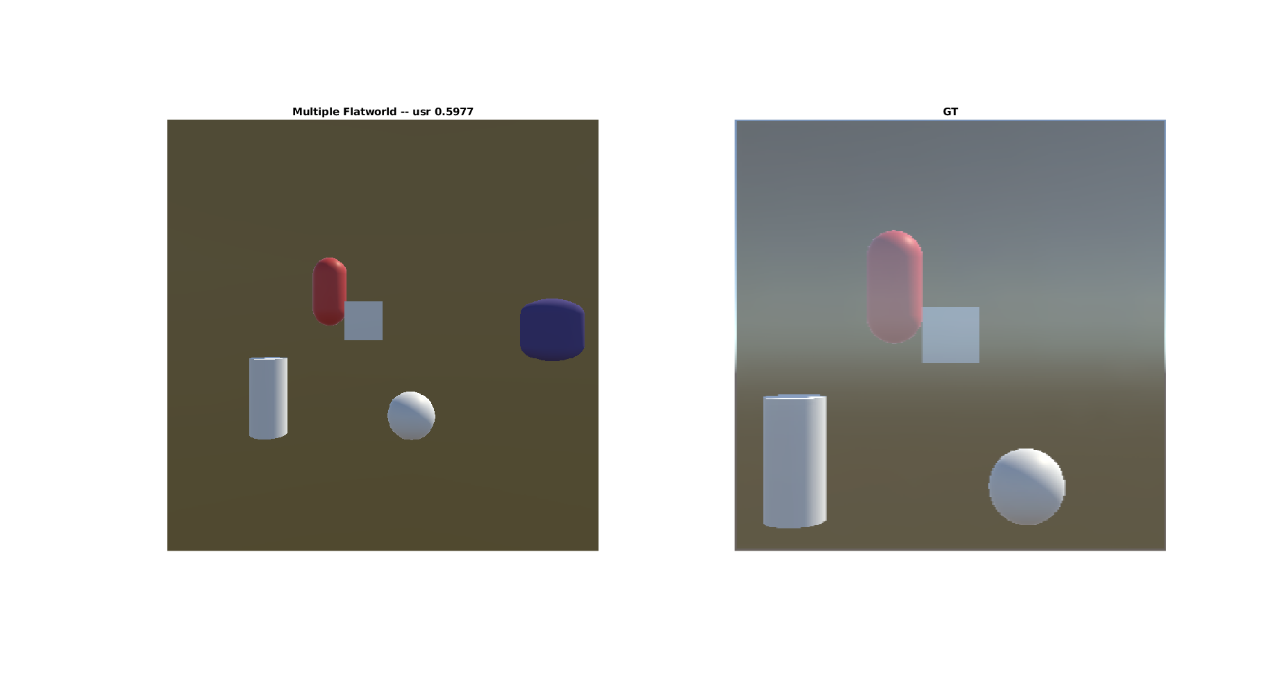
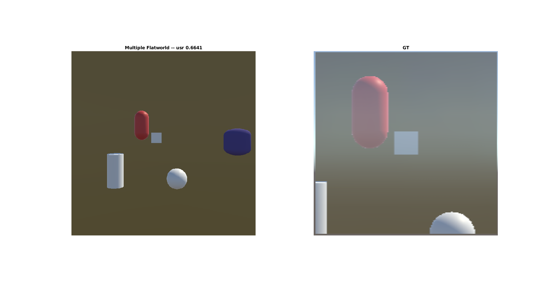
Results on TestBed: Multiple Flatworlds vs Flatworld vs Plane Mirror
-------------------------------------------------------------------------------
The following images are input to the system. Preliminary results are shown for usr at 3 different distances as calculated from retrieved depth map:


Results for FlatWorld vs Plane Mirror:
Results for MultiFlatworld vs Plane Mirror:
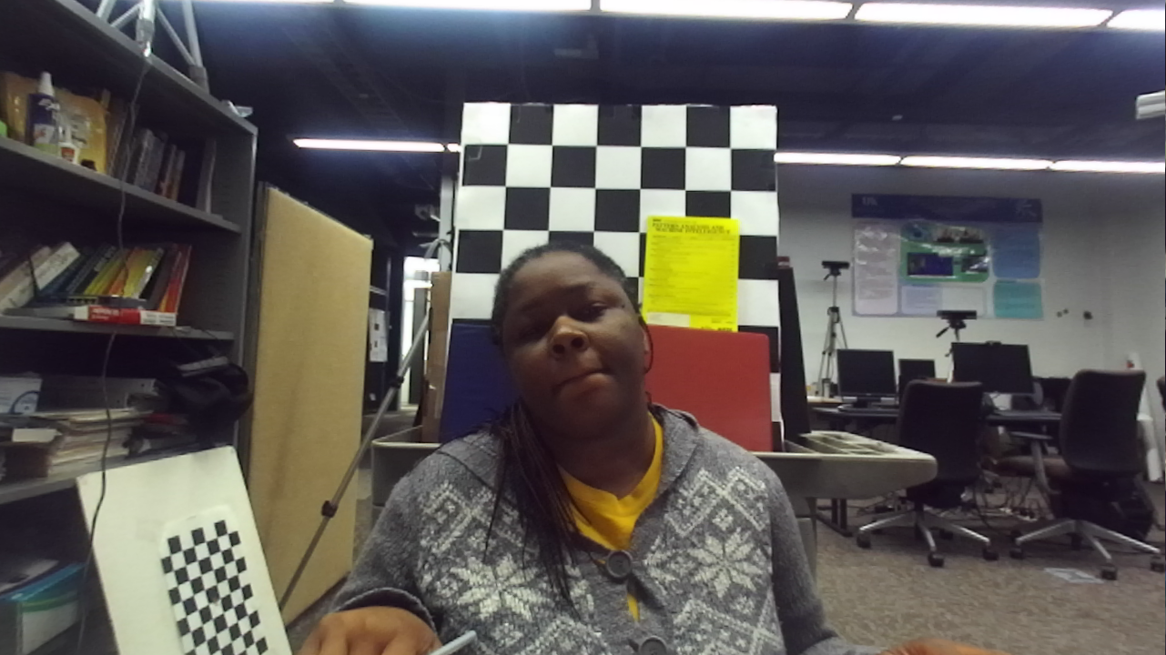
Applying it to a Real world Image, taken with StereoLabs ZED camera:
Input from Stereo:
 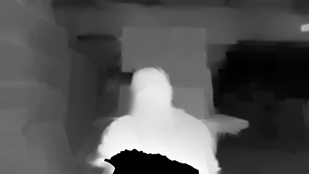
Results for FlatWorld:
![Figure [Flatworld_result]: Flatworld results](../assets/result_flat_135.png )
Results for MultiFlatworld:
![Figure [Multi_Flatworld_result]: 200 depth steps, Multi Flatworld results](../assets/result_multFlat_135_200steps.png )
![Figure [Multi_Flatworld_result]: 20 depth steps, Multi Flatworld results](../assets/result_multFlat_135_20steps.png )
Alternative Two: 2D scaling of background - Estimating the distance of user to Mirror
-------------------------------------------------------------------------------
Our present reflection equation is given in equation \ref{eqn:Reflection}. Let us define the **interaction zone** as the region in the environment with the user's face in front of the mirror and the user is at some distance between $d = d_1$ and $d = d_2$ where $d_2 \gt d_1$. The interaction zone is defined during calibration. It allows the user to view the mirror without seeing behind the mirror, and sets a region where the mirror visualizations should be cut off. We can see that several scenarios result:
1. If user is within an interaction zone, and background is far such that $Z \gg t_z$. This means $Z + t_z \approx Z$. Hence, equation \ref{eqn:Reflection} becomes: \begin{equation}
x_p = \frac{X_p}{Z_p} \approx \frac{d * ( \frac{Z_c * x_{pc}}{f})}{Z_c} = \frac{d}{f} * x_{pc}\\
y_p = \frac{Y_p}{Z_p} \approx \frac{d * ( \frac{Z_c * y_{pc}}{f})}{Z_c} = \frac{d}{f} * y_{pc}
\end{equation}
2. If user is within an interaction zone, and some of the background is near the user such that some distances $Z$ are of similar order to $t_z$. No change to equation \ref{eqn:Reflection}. However, we make an assumption here: that $Z_c + t_z \approx \alpha * Z_c$. Thus, for objects near the user in the image, we modify equation \ref{eqn:Reflection} such that we have:\begin{equation}
x_p = \frac{X_p}{Z_p} \approx \frac{d * ( \frac{Z_c * x_{pc}}{f})}{Z_c} = (\frac{d}{\alpha})\frac{1}{f} * x_{pc}\\
y_p = \frac{Y_p}{Z_p} \approx \frac{d * ( \frac{Z_c * y_{pc}}{f})}{Z_c} = (\frac{d}{\alpha})\frac{1}{f} * y_{pc}
\end{equation}
3. If user is too close or too far from mirror, then no visualization is put on mirror. Save us some work.
Several questions remain however.
First, how far must Z be for situations 1 or 2 above to hold. This is what I am currently working on in a unity3D simulation. In order to determine the value of d, a depth camera can be used.
Second, to generalize this to situations without the robomirror, what conditions must be set on $t_x, t_y, t_z, Z_c$, d or f to be able to use a 2D background and not a 3D model in creating this plane mirror.
Finally, if we only have a RBG (color) camera, with no depth sensing, how do we estimate d, $t_x, t_y, t_z, Z_c$ as these are all real-world coordinates.
In the next sections, we tackle these questions.
A few notes:
--------------------------------------------------------------------------------
1) $t_z$ can be written as $t_z = d - f$ due to the condition that the image plane of the camera coincides with the mirror plane. So, if we have d, and f, we can find $t_z$.
2) RGB camera setup will require extra calibration. In particular, it would require the accurate tracking of a reference point on the user's face, like a nose. This will ensure that $t_x, t_y$ can be calculated reliably if being used.
3) If we expect the user to center their faceIf, however, $t_x, t_y$ are very small, they can be eliminated from equation \ref{eqn:Reflection}, leaving us with robomirror equation.
Alternative Two: Conditions on Z, $t_z$,
--------------------------------------------------------------------------------
Alternative Two: Generalizing beyond the robomirror with a depth sensor and RBG cameras
--------------------------------------------------------------------------------
Alternative Two: Generalizing beyond the robomirror with a RGB cameras only
--------------------------------------------------------------------------------
Summary
-------------------------------------------------------------------------------
[TO DO]
[Click here](../index.html) to navigate back to home page.
**Bibliography**:
[#Francois13]: François, A. R., and Kang, E. Y. (2003, July). A handheld mirror simulation. In Multimedia and Expo, 2003. ICME'03. Proceedings. 2003 International Conference on (Vol. 2, pp. II-745). IEEE.
[#Lee17]: Lee, J. I., Kim, S., Fukumoto, M., & Lee, B. (2017, October). Reflector: Distance-Independent, Private Pointing on a Reflective Screen. In Proceedings of the 30th Annual ACM Symposium on User Interface Software and Technology (pp. 351-364). ACM.
[#Shen13]: Shen, J., Su, P. C., Cheung, S. C. S., & Zhao, J. (2013). Virtual mirror rendering with stationary rgb-d cameras and stored 3-d background. IEEE Transactions on Image Processing, 22(9), 3433-3448.
[#Shen12]: Shen, J., Cheung, S. S., & Zhao, J. (2012, December). Virtual mirror by fusing multiple RGB-D cameras. In Signal & Information Processing Association Annual Summit and Conference (APSIPA ASC), 2012 Asia-Pacific (pp. 1-9). IEEE.
[#Straka11]: Straka, M., Hauswiesner, S., Rüther, M., & Bischof, H. (2011). A free-viewpoint virtual mirror with marker-less user interaction. Image Analysis, 635-645.
[#Su17]: Su, P. C., Xu, W., Shen, J., & Cheung, S. C. S. (2017, July). Real-time rendering of physical scene on virtual curved mirror with RGB-D camera networks. In Multimedia & Expo Workshops (ICMEW), 2017 IEEE International Conference on (pp. 79-84). IEEE.